Show Posts

This section allows you to view all posts made by this member. Note that you can only see posts made in areas you currently have access to.


Messages - Cube

Pages: 1 ... 3 4 [5] 6
61
Here is the code:

Code: [Select]
void setup() {
Serial.begin(9600);

// -- LEDs and IRBS Initialization -- //

pinMode(BigGreenLED, OUTPUT);
pinMode(YellowLED, OUTPUT);
pinMode(IRBS_LED, OUTPUT);
pinMode(A0, INPUT);
pinMode(AD_Ready, INPUT);

// -- DIP Switch Shift Register Initialization -- //

pinMode(ploadPin, OUTPUT);
pinMode(clockEnablePin, OUTPUT);
pinMode(clockPin, OUTPUT);
pinMode(dataPin, INPUT);

digitalWrite(clockPin, LOW);
digitalWrite(ploadPin, HIGH);

DIPs = read_dip_switches();
display_dip_switches();
DIPSwitchValues = DIPs;

// -- AD7705 Initialization -- //

ad7706.reset();
ad7706.init(AD770X::CHN_AIN1, AD770X::CLK_DIV_1, AD770X::BIPOLAR,
AD770X::GAIN_1, AD770X::UPDATE_RATE_500);
        // Not using the second channel:
//ad7706.init(AD770X::CHN_AIN2, AD770X::CLK_DIV_1, AD770X::BIPOLAR,
// AD770X::GAIN_1, AD770X::UPDATE_RATE_500);

lcd.init();
lcd.backlight();
lcd.print("bbs.venturii.net");
}

void loop() {

static uint8_t x = 0;
static unsigned long as = 0, bs = 0, il_sum = 0;
unsigned int t = 0;

// Set Green LED to the value of the Data Ready pin from the AD7705:

digitalWrite(BigGreenLED, digitalRead(AD_Ready));
as += ad7706.readRawResult(AD770X::CHN_AIN1);

// IRBS - Take sample with LED On:

digitalWrite(IRBS_LED, HIGH);
digitalWrite(YellowLED, HIGH);
il_sum += 1023 - analogRead(A0);

// IRBS - Take sample with LED Off:

digitalWrite(IRBS_LED, LOW);
digitalWrite(YellowLED, LOW);
bs += 1023 - analogRead(A0);

x++;

// Oversample:
if (x > 14) {

// Display rad value from AD7705:
t = as / x;
lcd.setCursor(0, 1);
lcd.print(t);
lcd.print("     ");

// Display differential value from IRBS:
t = bs / x;
t = il_sum / x;
lcd.setCursor(7, 1);
if (il_sum > bs) {
lcd.print("[");
lcd.print((il_sum - bs) / x);
lcd.print("]   ");
} else {
lcd.print((bs - il_sum) / x);
lcd.print("   ");
}

// Clear buffers and counter:

as = bs = x = il_sum = 0;
}

// Lather, rinse, repeat. Always repeat.
}

62
The other AD7705 board does the same thing. :( Scratch that off the list.

Another piece of VERY odd behavior I've noticed is that when the AD7705 is locked up, the analog reading of the IR sensor affects the DataReady LED! I have NO idea how that happens, and if I disconnect the DataReady pin from the AD7705 it floats so the LED flickers, making me all but convinced that the signal is coming from the AD board. Every single time though, it does the same thing. It runs for a few seconds (30-90 it seems) and then the green LED goes out. Now if I place an object in front of the IR sensor and the value rises above 100 (seems to be exactly 100 that is the tripping point) (100 out of 1023, I might add.) - the green LED goes on. Dropping the value of the IR sensor below 100 extinguishes the LED, but all the while the AD7705 reports a value of 512. It is shifted two bits to the right, so I imagine this is probably 16385. Maybe I'll drop the bit shift off and see what the actual number is *just for something to try.* This is really bizarre. I can't wait until I'm reading this in retrospect with a smile on my face and thinking to myself, "If only I knew then what I knew now..."

63
Background / Preamble:

I'm working on a prototype PCB involving an AD7705 Analog to Digital converter, which I have been wrestling with over the past couple of hours. For my testing purposes, I've soldered together a little prototype PCB using socketed components and quite a few wires, housing the basic components. Some of the pieces, including the AD7705 are on external PCB's, as they come from Aliexpress that way. I've put together 6x header blocks on my PCB to connect to the various off-board modules in a star configuration using standard 4-pin connectors on each. This makes for some clean connections, and a fairly presentable package all things considered, as I will need to mount this thing in my house once I finish the hardware and software in the garage and begin collecting data and tuning all the working parameters before digesting all things learned and producing a PCB that has all these things onboard itself.

The prototype as it is uses an Arduino Pro Mini (one of the knockoffs I'm sure) and has a 2x16 LCD display on the I2C bus, the AD7705 on the SPI bus, a couple of LEDs for realtime feedback, and a TTL-to-USB adapter for updates and Serial Port monitoring. I have an Infrared sensor monitoring ambient IR levels using the Atmel 328's onboard ADC, and I'm feeding the whole assembly power off a regulated power supply with onboard digital voltage readout, dialed in at 5.1Vdc. When it starts up, the LCD initializes and displays the values from the AD7705 and the IR sensor (basically values from both ADC's oversampled 15x.) ... and nothing else.

Present Problem:

It works for several seconds to several minutes, and then the AD7705 reports a value of 512 and stops updating. I connected a wire to the Data Ready pin on the AD7705 board and mirror that pin on one of the status LED's. When things are working, that LED flashes rapidly. When it stops, the LED is extinguished, which means that the Data Ready pin is low. If I hit Reset on the MCU, it starts up and everything works again, but inevitably the AD7705 stops working after a number of seconds. During this time, the readouts from the onboard ADC continue on the display, so the MCU itself is not hung, I just do not know what is going on with the AD7705.

This is probably one of the many instances where an oscilloscope would be very useful, but I am left with print() and digitalWrite() statements in the meantime. Actually, one other thing I can test is that I have another AD7705 board, I will swap them and see if the other one does the same thing. I noticed that the Analog Voltage Reference IC on this one looks like it wasn't sitting properly when it got soldered and I think there are gaps between the pads and a few of the pins on it. Begin troubleshooting...

It's funny, these projects always get snagged in the wrong places. For example, I expected trouble getting it working with a different Chip Select pin, but once that was resolved and I started getting data from it, I thought I was out of the woods. Then I encountered seemingly high amounts of noise, so knocked a few bits of the ADC off (it is a 16-bit converter so fairly high precision, most of which is probably not necessary for my application.) Got the readings pretty stable and thought I was out of the woods again, ready to write [proper] firmware to begin interfacing this with the Venturii VDAC module - only to discover that the external ADC seems unstable. I don't want to move on from here until I have a proven platform I can fall back on in case the Venturii firmware is buggy, but now I am left troubleshooting something else I had not anticipated. So it goes...

64
Sensors / AD7705 16-Bit Analog to Digital (ADC) Converter
« on: October 10, 2015, 12:12:20 PM »
I've been scratching my head on this one for quite some time, and maybe someone can shed some light on this. I have an AD7705 16-Bit BiPolar Dual Channel Analog to Digital converter, which I am trying to incorporate into a prototype that I am building as part of my water meter project. Initial prototype on breadboard worked wonderfully, and there are posts about it on www.venturii.net. I've been building a perf board version, to make the circuitry a little more firm and to incorporate numerous other circuits and supporting gear as a firmware-proving platform. Out of curiosity, rather than any sort of necessity, I moved the chip select pin off of pin 10 and onto pin 4. In the AD7705 library there are static declarations for MISO, MOSI, CLK and Chip Select pins, and I changed the Chip Select pin designation from 10 to 4. No go. No matter what I tried, it would not work in this configuration, but if I choose pin 10 (and adjust wiring accordingly) it works perfectly. I've read posts on the Arduino forum and others where people have insisted that they've been able to get this to work, some claiming that you have to set the pin as an output before calling the SPI functions, which this library does, yet no matter what I've tried, it does not work on anything but pin 10.

As I said, this is fine on this project, I can use pin 10, I am just wondering if there is some way to use other pins for chip select (and have it actually work) as I've never been able to accomplish this seemingly simple and documented possible task.

65
General Discussion / Re: Your www.venturii.net - cool potal
« on: October 05, 2015, 02:53:20 PM »
Thank-you. Do you have an interest or background in automation or integration? How did you find the Venturii blog and this forum?

- John

66
VDAC-NIM-1 / Pre-Prototype Prototype Built
« on: October 02, 2015, 10:35:11 PM »
So before I put through a $400 PCB order, I wanted to "pre-test" a few of the circuit designs that I put into the NIM-1. It's simple things, but I want to make sure that everything will work "the way I think it will" before making such a commitment and investment. This also forces advancement of the VDAC firmware, which will form the heart of the NIM-1. I am also pretty excited to "announce" that I may have found a way to incorporate OWI code into VDAC in such a way that the other OBD types will not get starved for attention and potentially miss important updates.

The first update to the VDAC firmware will actually be a pretty major one; implementation of what I've been calling the "Multi-Drop Firmware" to allow the creation and deployment of [smaller|purpose-built|multiple] VDAC boards together on the same 4-wire bus (GND, +12VDC, RS485A, RS485B). I wrestled back and forth with the idea of making every single device Ethernet / WiFi enabled, and that is still an option where the application warrants it, but there are certainly places throughout my house where it makes far more sense to simply run a 4-wire bus between multiple modules all tied back to a single NIM or even directly into a USB port or 485-Ethernet/WiFi adapter.

I've ordered quite a few parts from China today to begin testing specific circuits that form the NIM-1. My goal is to prove each circuit before the PCB run as it is quite expense and I've already caught a number of glitches / mistakes / omissions / problems through this process. It may even inspire me to add support for a number of other devices via pin headers for future expansion or user options. One such idea is the incorporation of a display port, for something like a 2x16 or 4x20 LCD display, or maybe even something simpler like one of those TM1638-based LED/Button interfaces; the possibilities are endless. I love this stuff!

67
General Discussion / Minigroup Shutting Down
« on: October 02, 2015, 10:04:27 AM »
I received an email from Minigroup yesterday announcing that they will be shutting their service down at the end of October. We had been using Minigroup for Venturii discussions, among other things, over the past couple of years and it was a decent service. There were a few things that it lacked, (Two come to mind off the top of my head: 1. Their message editor did not have the ability to preview messages before you posted them, and 2. Only the first message in a conversation thread would display images - all comments below it did not and I don't think there was a way to [force] it to either.)

I'd like to grow this forum into a bustling place to discuss automation and integration topics. So please, tell your friends, ask your questions and let's get this automation party started!

John

68
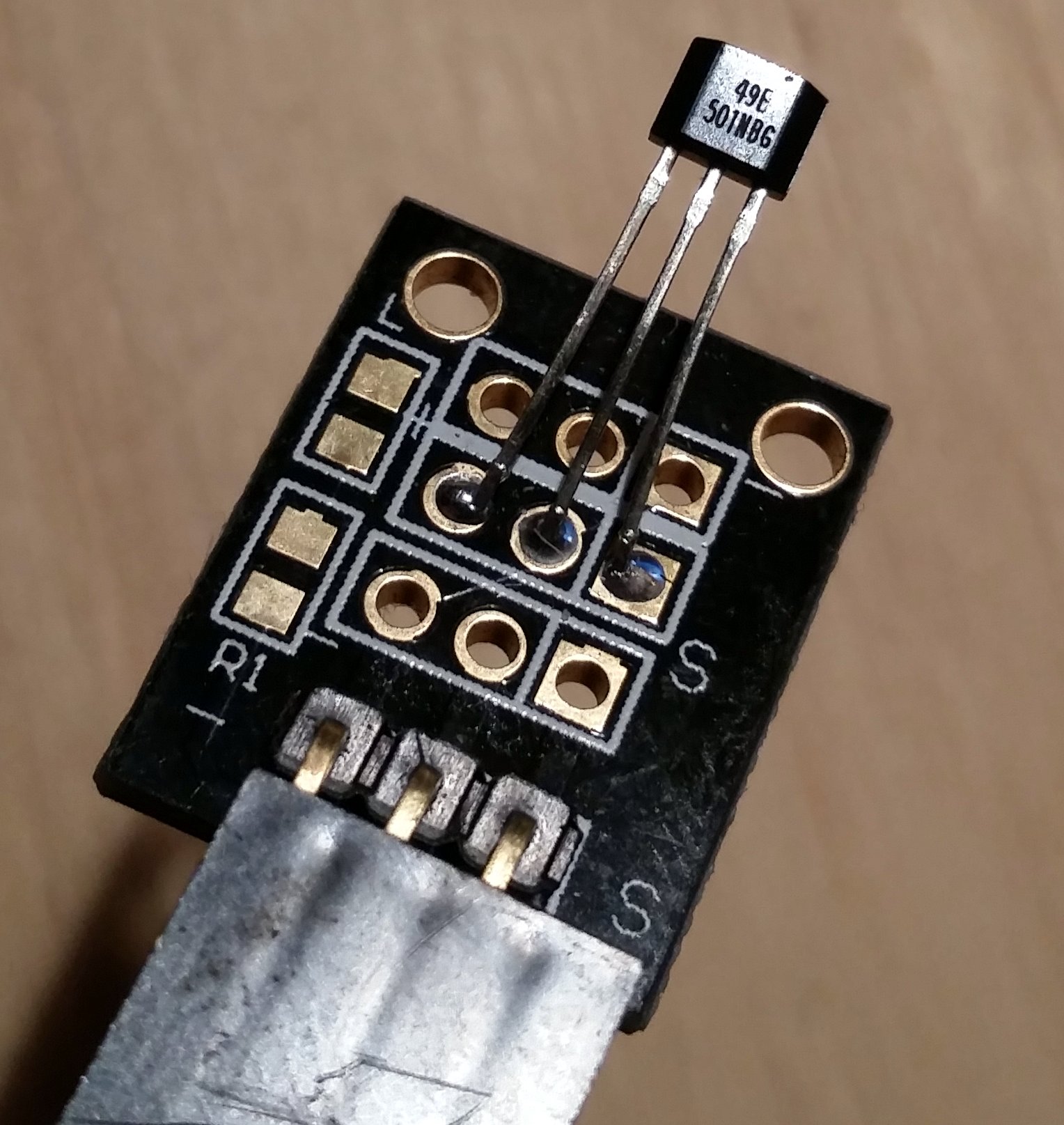
Last night I confirmed a very exciting theory. Using a simple SS49E Hall Effect Sensor taped to the body of my Badger Water Meter, I was able to capture VERY detailed flow data as the magnets within the body of the water meter rotated proportionally to the amount of water flowing through it. For example, here is what I read from the sensor when using a very small amount of water:


And here is what I read from the SS49E sensor while using a fairly moderate amount of water:


The sensor itself came to me as part of an assorted sensor kit purchased from AliExpress:


Data was captured using an AD7705 16-Bit BiPolar Analog-To-Digital (ADC) Converter with a 500Hz sample rate. I will have to incorporate support for this ADC board into the VDAC Firmware as I have a few other planned uses for it on other projects. It certainly performed VERY nicely in this little experiment, and I am very excited to begin using it for other data capture application in the near future.

A much more detailed writeup on this experiment, including some of the history behind it, can be read on the Venturii Adventure Blog at http://www.venturii.net/blog/2015/10/01/measuring-water-magnetically/

- John

69
The Sun XTender battery is definitely toast, I hooked up a standard 12v 7 AmpHour battery in it's place and I get about 3 and a half hours of run time, far out-lasting the PVX-340T which is down to running for about 1 hour / night. I tied in a transfer switch this morning to select which battery supplies power to the outside lights, and tonight I'm going to see how long the Optima Red I have in the second battery slot runs this 2 amp load for. Unfortunately I couldn't find the correct resistors to build another voltage divider for measuring the voltage of the second battery... I guess I'll have to resort to current for the time being.

The other day I pulled in a new 10 AWG conductor to the back deck controller. Originally I was going to run all the outside lights on a single circuit, but then it occurred to me that if I need to supplement the batteries with AC power supplies, I might need a heck of a power supply to provide for all the load. By splitting up power supplying both controllers, I can power them together off the battery if need be, but separately off [smaller] AC power supplies without having to go to a monster. Yes, there may be efficiency in doing so, but there is also cost if I have to buy a power supply I don't already have. ;)

70
Decider / New Feature - TORX Time Definitions
« on: September 26, 2015, 06:18:53 PM »
Decider 0.5.0-459 marks a key new feature, one which has long been on my wish list. It gives Decider a number of new capabilities for scheduling things to happen, and it also incorporated an idea I've been meaning to implement for years. In order to appreciate the Torx Timer, you have to understand the history. For that, let me begin with a story.

When I was a little boy, my father and I used to collect stuff from commercial and industrial bins around the city. You simply would not believe some of the items that people threw out in those days, and my collection quickly grew to include all manner of security systems, built-in vacuum cleaner parts, intercom systems, cameras, sensors, motors, switches, speakers, transformers, tools, amplifiers, sprinklers, light fixtures, humidifiers (both ultrasonic and steam) - the list was nearly without end. Some things needed minor repair, but most worked as we found them. One such find was a brand new Tork 7102 mechanical timer. It had never even been powered up, nor had any of the knockouts been punched. It was brand new, in it's box.


Anyone who's ever managed a building has seen or set one of these things, knows of their simplicity and reliability. I put a cord and a plug on mine so that I could use it to control the operation of things around the house, and it's probably still in one of my dad's sheds to this day. I'd even reckon that were I to find it, it would probably still work. You control the load by screwing little Pegs onto a wheel with markings indicating time of day within a 24 hour period. White pegs switch the load on, black pegs switch the load off. A special copper wheel (to the bottom-left of the main wheel) allows you to install or remove additional pegs to specify days of week for operation. A simple description of what it could do might be written like this: Turn the load on at 7:00 PM and off at 6:00 AM, Monday through Friday.

Up until now, all of the time definitions within Venturii have been stateful. In other words, they have a start and an end point in time. Day of Week has a Value Interpreter that becomes a 1 at midnight on any day that is selected in it's configuration, and becomes a 0 at midnight on any days NOT in it's configuration. Hour periods have a start and end time, as do Month of Year, Absolute Time Periods, etc. While excellent at making sure plants are watered for 30 minutes every morning at 4:00 on Mondays, Thursdays and Saturdays, these time definitions do not allow you to configure something that happens every ten minutes. They also require something like a comparison to attach commands to them. The comparison evaluates the value of the time period, and then executes different commands based on whether that time period is true or not. I have an amplifier for my whole home audio system that I'd like to make sure gets turned off every day. Everyone in the house knows how to turn it on when they want to listen to music, but no one remembers to turn it off. I don't want to turn it on automatically, but I would like to turn it off automatically as it draws half an amp (~60 watts) when idle. I could set up an hour period and a comparison with a command that executes only when the time period becomes true to turn the amp off at 11:00 pm every night, but it feels a bit clumsy.

Perhaps the biggest motivation for creating the Torx timer has, like all good features, been invented to solve a problem. We have this requirement at work to sign in and out every day by sending an email to the office, telling them where you're working for the day so they know where to start looking if you don't make it home. It's a good idea in theory, however if you haven't signed in by 9:00 am, and haven't signed out by 4:45 pm, the office staff send an email to your supervisor tattling on you for your negligence. The problem I've had with this system is that I work 9-5 or later, sometimes 6 or 7. What's worse is that I'm often IN the office, around a glass wall from the people tasked with policing the sign in board. In latter weeks they've grown accustomed to walking around that corner and seeing if I'm still at the office, but still sign me out regardless of whether I'm done working for the day or not. That system is completely broken. What I've been doing is using Venturii to send my sign in and out emails to the office, which has saved me no end of grief (except one time when I forgot to inhibit it on a long weekend. Oops! haha) Even so, I wondered if someone might notice that my messages to sign in and out came at [exactly] the same time, every day.

A summary of the features of the new Torx Timer system in Decider is this:

  • 24-hour Timing Cycle, perfect for things that need to happen at certain times each day.
  • A single timer can have an unlimited number of Pegs.
  • Each Peg has a fixed time, with microsecond resolution.
  • Each Peg can have a repeat interval, and repeat limit, allowing you to execute that peg's commands at recurring intervals in a single construct.
  • Each Peg can randomly deviate up to a set number of seconds before and/or after the set time, solving the Home Alone problem.
  • Each Peg can have an unlimited number of commands to execute.
  • Each Peg uses the Condition / Inhibitor system for allowing / blocking execution based on other Value Interpreter values.
  • The commands in each peg can be manually executed at the command prompt or from within other objects in Decider.

The Random Deviation functionality has been an idea I've been toying with for a long time, which may see itself emerge in some of the other time definition constructs as well. It solves what I call the Home Alone problem with traditional timers. If you remember the movie, the burglars had memorized when the lights in each house turned on, confirming the vacancies of those premises. By incorporating a random deviation to the set time of any given Peg, you can obtain a more unpredictable result while still maintaining the convenience of automation. Random Deviation has two parameters, number of seconds before the peg time and number of seconds after the peg time to randomly deviate. This allows you to constrain the behavior to something like "Turn on the lights AFTER 6:00 PM but before 7:00 PM." The CONDI integration allow each peg's command execution to require meeting a set of conditions and clear a list of inhibitors, giving you the ability to constrain operation to certain days of the week, times during the year, or only if any other Value Interpreter is a certain value or not a certain value. The repeat feature provides an easy way to do things at regular intervals like resetting counters or sending status emails.

As with many of the features I've come up with, I can't wait to see how other people find interesting uses for them that I had never even considered.


71
Wish List / Intention
« on: September 20, 2015, 01:58:40 AM »
This is where I'd like to host a list of feature requests for Venturii hardware, software and firmware. I'm sure once Mark gets here that he will jump on the "Max Log Gap" feature he's been asking about for months. (I will re-assure you, Mark, it is coming. It's on the road map and I've worked out exactly how I will implement it.) As for other requests, I have a list myself that's three miles long. Having a place to document them, clarify their intent and journal the progress to their achievement is important.

72
I have been using a Sun XTender PVX-340T battery with my solar system. During most days, the solar panel on my roof collects more than enough power to fully charge the battery, and once the sun goes down, the battery supplies power to 2 amps of my outdoor lighting - basically one of my tree beds. The tree bed has three LED spot lights (250mA each @ 12V) and one path light that uses one 11w incandescent bulb (1A @ 12V).

I'm writing this but fear I already know the answer. Since the system was put in, I've had current detection sensors installed on both batteries and the solar panel itself, measuring the amount of current flowing into and out of each battery, and from the panel itself. Only recently did I add a voltage measuring circuit to the VDAC in the garage connected with this setup, and began monitoring the voltage of the main battery I am concerned with, the PVX340T.

I've had the system operating basically on a photocell - when the ambient light level dropped outside below a certain threshold, a relay kicked on, turning on the outside lighting. Once the sun came up the next morning, the relay turned off, and the solar panel & controller took care of restoring charges to both batteries. I do keep mentioning a second battery, but it is not important to this conversation; it is not connected to this load in any shape or form, and the solar charging controller is configured to give 100% charging priority to the PVX-340T, and my measurements with the current sensors seem to confirm this.

We had a week of gloomy weather: Dim, rainy days and dark stormy nights. I was not paying attention, and the system essentially left the load attached to the battery throughout each night. The incandescent bulb in particular, just burned away every last electron that battery had within it.

All of a sudden it occurred to me that this was not good, so I built a voltage monitoring circuit and set up conditions in Venturii to drop the load if the battery voltage reached 10.5 volts, which seems to be the "empty" mark of a 12v battery. Venturii now logs the voltage and current for the battery, but I am finding that it is now dropping below 10.5 volts after only running for about 2 hours whereas before it seemed to last all night without any trouble. Does this mean that my battery is dead? It basically starts rejecting power very early in the day, and dies very quickly at night. Rated as a 34 amp-hour battery, it now seems to be a 4 amp-hour. Can anyone tell me what I already know?

73
Sensors / Re: HC-SR04 Ultrasonic Range Finder - Random Readings in a Tank
« on: September 19, 2015, 04:49:11 PM »
Sigh. A quick search on Google for water softener icons came back to a site describing the exact same solution to water softener salt level reading, using an ultrasonic sensor and all. (Different model, mind you...) Here I thought I figured this one out all on my own. Well, I guess I did - it just turns out I am not the first person to do so... That, and they also have created an icon for depicting the salt tank level. Theirs uses flash though, so I am going to stay away from that and see if I can come up with my own method in HTML5 to make it much more portable and accessible.

74
Sensors / Re: HC-SR04 Ultrasonic Range Finder - Random Readings in a Tank
« on: September 19, 2015, 04:44:38 PM »
Several days running and the readings have stayed within a 3 mm (yes, three millimeter) reading! Tonight the water softener is set to do a regeneration cycle; it will be interesting to see if the salt shifts as a result. Next up I need to find a good way to display this new-found data source; there aren't a lot of water softener icons out there...

75
Sensors / Re: HC-SR04 Ultrasonic Range Finder - Random Readings in a Tank
« on: September 17, 2015, 09:40:36 PM »
Re-checked the power. Voltage at the sensor was 3.4 VDC. Re-wired the power upstream and it's solid as a rock now. Sigh. Good thing to know for next time I guess. And, I can now monitor my salt levels!  :)

Pages: 1 ... 3 4 [5] 6